ДОМАШНЯЯ ЛАБОРАТОРИЯ
Полезный чердак. ARDUINO UNO + XBee
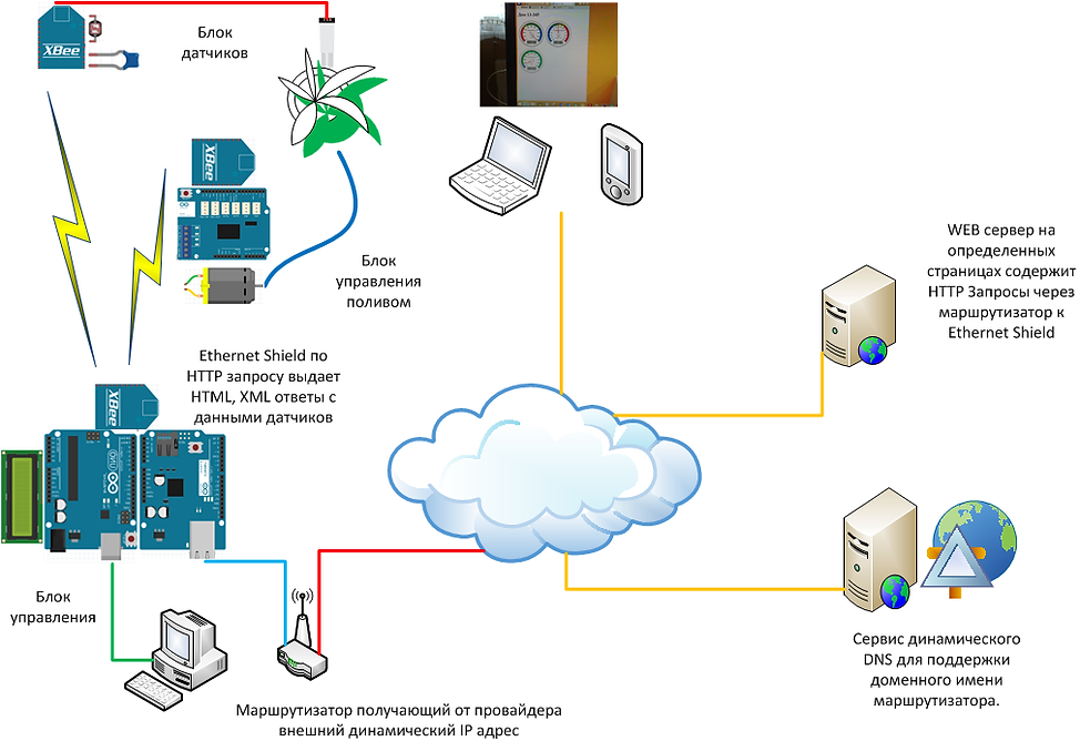
Центром Блока управления является программа работающая под управлением Arduino UNO. Она управляет получением данных с датчиков температуры, освещенности, влажности из Блока датчиков и выводит данные на LCD дисплей, одновременно на WEB сайт опубликованный в Интернет. Для "общения" с Интернет используется Ethernet Shield. При совпадении установленных параметров температуры, влажности, освещенности, включается полив. Например, ночью или при температуре +5 градусов и ниже, полив не включится. Из блока управления посылается команда Блоку управления поливом, включить насос. По достижении установленного уровня влажности вновь посылается команда на выключение насоса. Минимальные и максимальные значения влажности, температуры, освещенности устанавливаются при помощи кнопок с визуализацией на LCD дисплее, эти параметры также отображаются на страничке сайта. Далее программа отслеживает эти параметры. Интерфейс с компьютером необходим только для перепрошивки новых версии программ, ну и для тестовых промежуточных работ. В боевом режиме Блок управления работает самостоятельно.

 |  |  |
|---|---|---|
 |  |  |
 |  |  |
 |  |  |
Настройка XBee модулей.
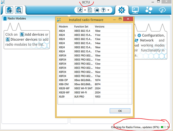
На сайте производителя есть дистрибутив X-CTU, который очень удобен в настройке радиомодулей и тестированию по радиоканалу. Подключите питание всех своих устройств. Координатор при помощи специального интерфейса подключите к компьютеру с программой X-CTU. В некоторых случаях можно восстановить XBee если его не "видно" из утилиты X-CTU. При запуске X-CTU происходит поиск последних обновлений прошивки XBee модулей. Здесь рассматривается вариант, когда установлен ID PAN ID. Это так же будет справедливо и для устройств с заводскими установками. Свой ID PAN ID Вы установите позже при редактировании параметров для создании своей выделенной сети.
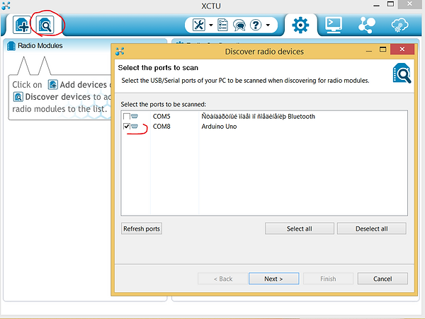
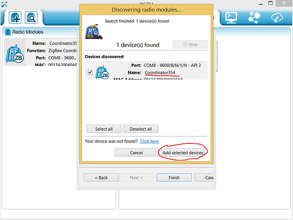
Необходимо выбрать USB порт на котором подключен XBee-USB адаптер с XBee модулем Coordinator.
Параметры протокола обмена информацией оставляем по умолчанию так:

Если все в порядке подключение пройдет успешно.
Теперь можно просмотреть и отредактировать настройки. ID PAN ID Вам нужно установить свой. Локальные адреса XBee SH и SL устанавливаются автоматически. Одинаковый ID PAN ID необходимо установить в настройках Ваших роутеров. Параметры у всех должны быть одинаковыми, за исключением NI Node Identifier, у каждго должно быть уникальное имя. Таким образом у Вас будет не широковещательная сеть.

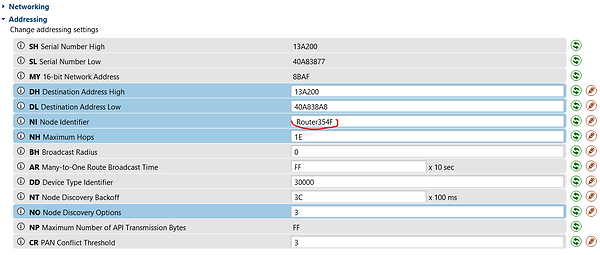
Очень важно!!! Параметр AP API Enable должен быть установлен в 2 на всех устройствах.

Если на роутерах установлены одинаковый PAN ID то при помощи Поиска Вы найдете все включенные устройства XBee Вашей сети.
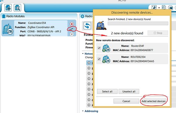
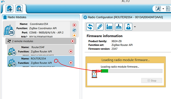
Кликнув мышью по пиктограмме устройства, по радиоканалу загрузится его конфигурация.
Кликнув на соответствующую пиктограмму Вы сможете построить графическое представление Вашей сети.

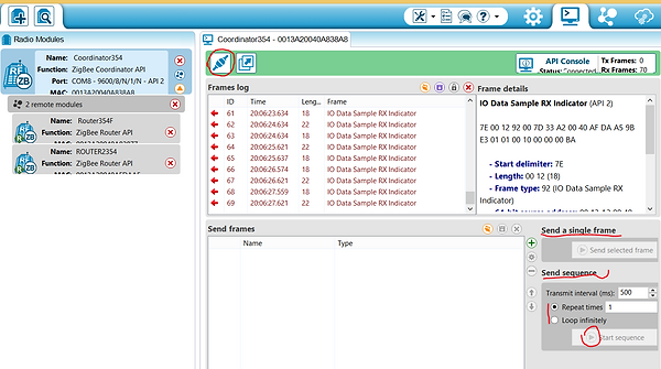
Кликнув на соответствующую пиктограмму Вы сможете посмотеть трафик и содержание сетевых пакетов. Сформировать свой пакет с нужной вам командой (спецификацию команд смотреть в документации XBee) и создать цикл команд. Программа поможет Вам сформировать правильный сетевой пакет команды.

Основные принципы программирования XBee и написания программного кода.
Здесь не все так просто. Имеется множество вариантов. Мне подошел один, это режим команд в API режиме. Если кто то знает больше вариантов которые практически реализованы для многих XBee и сможет об этом рассказать пожалуйста пишите. Знаю, что многие будут Вам за это благодарны. И так пояснения исходного кода который можно скачать в соответствующем разделе сайта:
Объявление массива данных для получения 5 аналоговых и 13 цифровых значений пинов со ВСЕХ подключенных в Вашу сеть XBee. Правда неожидано?
int dataAnalog[5] = {0,0,0,0,0};
int dataDigital[13] = {0,0,0,0,0,0,0,0,0,0,0,0,0};
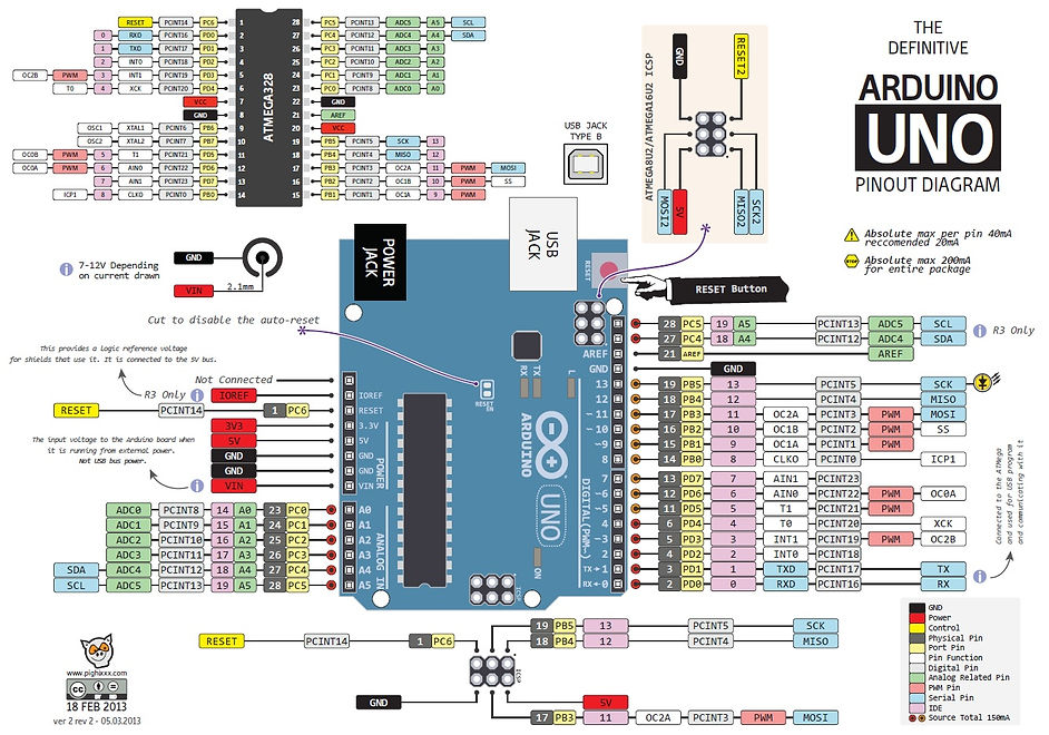
Настранице 32 "Описание на русском модулей RF Xbee" (это ссылка в конце блога),есть таблица 4-08 "Настройка каналов вода-вывода". Команда D4 означает подать команду на пин 11 DIO4 модуля XBee.
uint8_t Cmd4[] = { 'D', '4' };
На странице 33 той же документации есть таблица 4-09 Настройки параметров выводов. Параметр 0x04 устанавливает цифровой сигнал вывода в низкий. 0x05 в высокий.
uint8_t ValueOff[] = { 0x04 };
uint8_t ValueOn[] = { 0x05 };
Эта часть кода отвечает за настройку адреса роутера, который управляет 11 пином для включения-выключения реле управления насоса. Адрес, это обыкновенный MAC адрес прошитый на заводе. Его Вы можете увидеть в утилите управления XBee. Это параметры SH и SL.
Если вам нужно управлнять многими XBee, то вам нужно создать дополнительные объекты. Например remoteAddress1 но адресом другого XBee и соответственн remoteAtRequest1, и так далее.
XBeeAddress64 remoteAddress = XBeeAddress64(0x0013a200, 0x40afdaa5);
RemoteAtCommandRequest remoteAtRequest = RemoteAtCommandRequest(remoteAddress, Cmd4, ValueOff, sizeof(ValueOff));
Создание этого объекта и далее код отвечает, ВНИМАНИЕ, только за прием 5 аналоговых и 13 цифровых значений пинов со ВСЕХ подключенных в Вашу сеть XBee.
RemoteAtCommandResponse remoteAtResponse = RemoteAtCommandResponse();
void ReadXbee()
{
xbee.readPacket();
if (xbee.getResponse().isAvailable())
{ if (xbee.getResponse().getApiId() == ZB_IO_SAMPLE_RESPONSE)
{ xbee.getResponse().getZBRxIoSampleResponse(ioSample);
.......
Для того что бы отделить мух от котлет и определить адрес пакета роутера пришедшего из Вашей сети на координатор, Вы можете определить адрес XBee и обработать его. В данной реализации проекта это не требуется, так как только один XBee снимает показания датчиков температуры и освещения с определенных пинов. Вы также получаете состояние цифрового сигнала со второго XBee управляющего реле. Но и он в данном проекте не обрабатывается. Коментарии сделаны из экономии оперативной памяти. Вывод данных на экран через UART съедает много ресурсов.
//Serial.print(ioSample.getRemoteAddress64().getMsb(), HEX);
//Serial.print(ioSample.getRemoteAddress64().getLsb(), HEX);
Здесь часть кода проверяющего Пришли аналоговые данные? Пришли цифровые данные?
if (ioSample.containsAnalog())
{ //Serial.println("Sample contains analog data");
}
if (ioSample.containsDigital())
{ //Serial.println("Sample contains digtal data");
}
Запись в буфер аналоговых данных С ОПРЕДЕЛЕННОГО АДРЕСА
for (int i = 0; i <= 4; i++)
{ if (ioSample.isAnalogEnabled(i))
{
dataAnalog[i] = ioSample.getAnalog(i);
}
}
Запись в буфер цифровых данных С ОПРЕДЕЛЕННОГО АДРЕСА
for (int i = 0; i <= 12; i++)
{ if (ioSample.isDigitalEnabled(i))
{
dataDigital[i] = ioSample.isDigitalOn(i);
}
}
Стандартная функция посылки AT команд. Вообще то здесь в поянениях взят код приведенный в примерах IDE Arduino
void sendRemoteAtCommand() {
//Serial.println("Sending command to the XBee");
// send the command
xbee.send(remoteAtRequest);
Ну а здесь собственно передачи команды на включение-выключение реле насоса. Устанавливается высокий-низкий уровень цифрового сигнала на пине 11 XBee. Обратите внимание на объект remoteAtRequest (наверху выделен зеленым цветом), он вначале создавался под определенный адрес с низким уровнем цифрового сигнала.
void watering_on()
{
remoteAtRequest.setCommand(Cmd4); //передать радиокоманду на включение насоса
remoteAtRequest.setCommandValue(ValueOn);
remoteAtRequest.setCommandValueLength(sizeof(ValueOn));
sendRemoteAtCommand();
}
void watering_off()
{
remoteAtRequest.setCommand(Cmd4);
remoteAtRequest.setCommandValue(ValueOff);
remoteAtRequest.setCommandValueLength(sizeof(ValueOff));
sendRemoteAtCommand(); //передать радиокоманду на выключение насоса
}
В этой части кода читается из буфера данные и отображаются на экранчике LCD дисплея.
ReadXbee(); // Чтение данных с XBee модулей в буфер
if(pause(interval) == HIGH)
{
lcd.setCursor(0, 1);
lcd.setCursor(0, 1); lcd.print(" "); lcd.setCursor(0, 1); lcd.print(dataAnalog[1]); //hu
lcd.setCursor(5, 1); lcd.print(" "); lcd.setCursor(5, 1); lcd.print(dataAnalog[2]/10.0);
lcd.setCursor(11, 1); lcd.print(" "); lcd.setCursor(11, 1); lcd.print(dataAnalog[3], DEC); //il
pubweb(); // пересылка данных в Интернет
}
Все коды взяты из примера билиотеки XBEE поставляемой с IDE Arduino.
Ссылки на полезные статьи:
Описание библиотек разработки на русском языке
Arduino+WEB+Ethernet Shield+Gauge
Что такое XBee, красивые примеры
Страничка производителя XBee с дистрибутивами и базой знаний
Разрешение проблемы приема передачи для многих XBee
Исходные коды и схемы. Оперативная память UNO ограничена.
ARDUINO UNO + XBee + AJAX