HOME LABORATORY
Useful attic. ARDUINO UNO + XBee
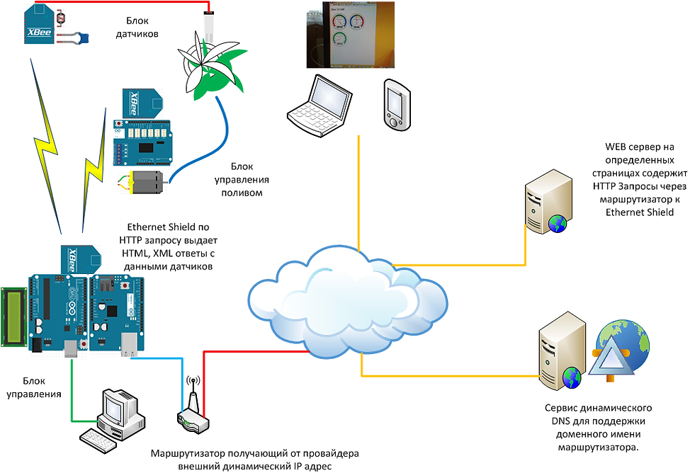
The center of the Control Unit is a program running under Arduino UNO. It manages the receipt of data from temperature, light, humidity sensors from the Sensor Unit and displays the data on the LCD display, at the same time on the WEB site published on the Internet. Ethernet Shield is used to "communicate" with the Internet. If the set parameters of temperature, humidity, illumination coincide, watering is switched on. For example, at night or at a temperature of +5 degrees and below, irrigation will not turn on. A command is sent from the control unit to the irrigation control unit to turn on the pump. When the set humidity level is reached, a command is sent again to turn off the pump. The minimum and maximum values of humidity, temperature, illumination are set using buttons with visualization on the LCD display, these parameters are also displayed on the site page. Then the program monitors these parameters. An interface with a computer is required only for flashing new versions of programs, and for test intermediate works. In combat mode, the Control Unit works independently.

 |  |  |
|---|---|---|
 |  |  |
 |  |  |
 |  |  |
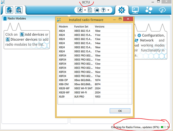
Configuring XBee modules.
The manufacturer's website contains the X-CTU distribution kit, which is very convenient for configuring radio modules and testing over the radio channel. Connect the power to all your devices. Connect the coordinator to the computer with the X-CTU program using a special interface. In some cases, you can restore the XBee if it is not "visible" from the X-CTU utility. When X-CTU starts, it searches for the latest firmware updates for XBee modules. This is the case where the PAN ID is set. This will also be true for devices with factory settings. You will set your ID PAN ID later when editing the parameters to create your own dedicated network.
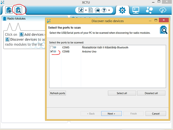
It is necessary to select the USB port where the XBee-USB adapter with the XBee Coordinator module is connected.
We leave the parameters of the information exchange protocol by default as follows:

If everything is in order, the connection will be successful.
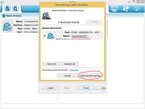
You can now view and edit the settings. ID PAN ID You need to set your own. The local addresses of the XBee SH and SL are set automatically. The same ID PAN ID must be set in the settings of your routers. All parameters must be the same, except for the NI Node Identifier, each must have a unique name. This way you will not have a broadcast network.

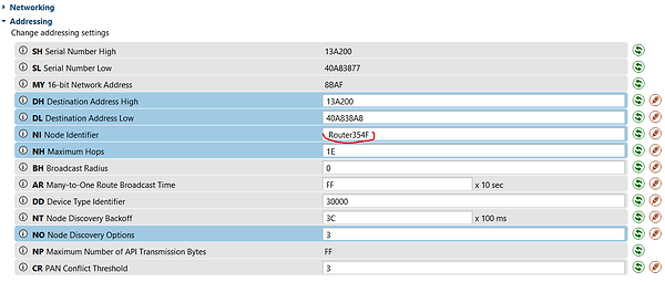
Very important!!! The AP API Enable parameter must be set to 2 on all devices.

If the routers have the same PAN ID, then using Search you will find all enabled XBee devices on your network.
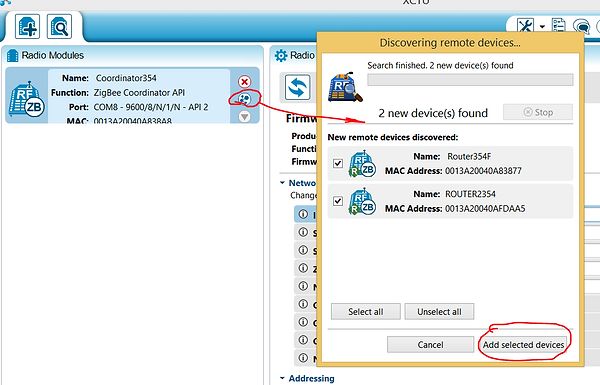
By clicking on the device icon, its configuration will be loaded over the radio channel.
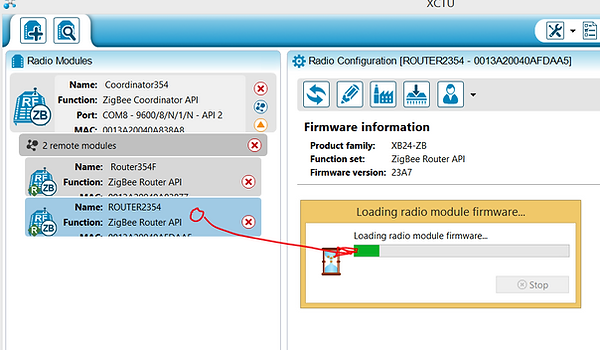
By clicking on the corresponding icon, you can build a graphical representation of your network.

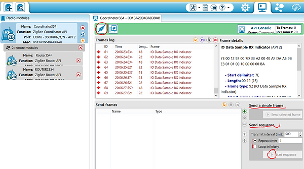
By clicking on the corresponding icon, you can view the traffic and the contents of network packets. Form your package with the command you need (see the XBee documentation for the command specification) and create a command cycle. The program will help you to form the correct network command package.

Basic principles of XBee programming and coding.
Not everything is so simple here. There are many options. One came up to me, this is the command mode in the API mode. If someone knows more options that are practically implemented for many XBee and can tell about it, please write. I know that many will be grateful to you for this. And so the explanations of the source code that can be downloaded in the appropriate section of the site:
Declaring a dataset to get 5 analog and 13 digital pin values from ALL connected to your XBee network. Isn't it unexpected?
int dataAnalog [5] = {0,0,0,0,0};
int dataDigital [13] = {0,0,0,0,0,0,0,0,0,0,0,0,0};
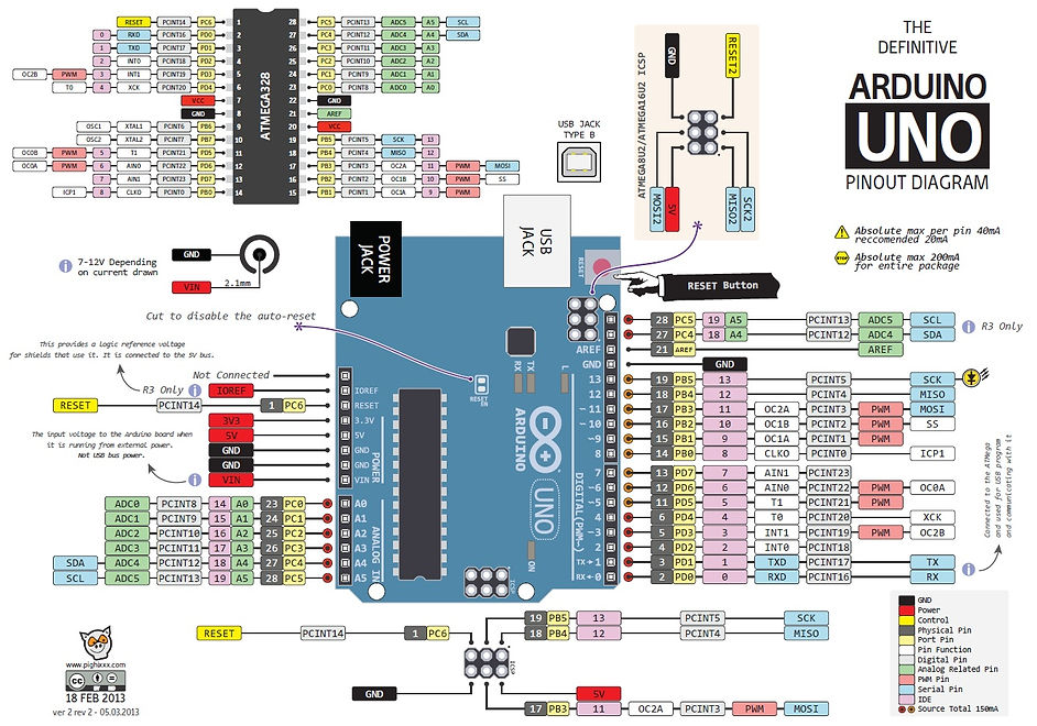
On page 32 "Description in Russian of RF Xbee modules" (this is the link at the end of the blog), there is table 4-08 "Configuring I / O channels". Command D4 means to issue a command to pin 11 of DIO4 of the XBee.
uint8_t Cmd4 [] = {'D', '4'};
On page 33 of the same documentation, there is Table 4-09 Pin Parameter Settings. Parameter 0x04 sets the digital output signal to low. 0x05 to high.
uint8_t ValueOff [] = {0x04};
uint8_t ValueOn [] = {0x05};
This part of the code is responsible for setting the address of the router, which controls 11 pins to turn on / off the pump control relay. The address is an ordinary MAC address that is stitched at the factory. You can see it in the XBee management utility. These are SH and SL parameters.
If you need to control many XBee's, then you need to create additional objects. For example remoteAddress1 but the address of another XBee and the corresponding remoteAtRequest1, and so on.
XBeeAddress64 remoteAddress = XBeeAddress64 (0x0013a200, 0x40afdaa5);
RemoteAtCommandRequest remoteAtRequest = RemoteAtCommandRequest (remoteAddress, Cmd4, ValueOff, sizeof (ValueOff));
The creation of this object and further the code is responsible, ATTENTION, only for receiving 5 analog and 13 digital pin values from ALL XBee connected to your network.
RemoteAtCommandResponse remoteAtResponse = RemoteAtCommandResponse ();
void ReadXbee ()
{
xbee.readPacket ();
if (xbee.getResponse (). isAvailable ())
{if (xbee.getResponse (). getApiId () == ZB_IO_SAMPLE_RESPONSE)
{xbee.getResponse (). getZBRxIoSampleResponse (ioSample);
.......
In order to separate the flies from the cutlets and determine the address of the router packet that came from your network to the coordinator, you can determine the XBee address and process it. In this implementation of the project, this is not required, since only one XBee takes readings of temperature and lighting sensors from certain pins. You also get the digital signal status from the second XBee control relay. But it is not processed in this project either. Comments are made to save RAM. Displaying data to the screen via UART eats up a lot of resources.
//Serial.print(ioSample.getRemoteAddress64 (). GetMsb (), HEX);
//Serial.print(ioSample.getRemoteAddress64 (). GetLsb (), HEX);
Here is a part of the verifier's code. Analog data received? Did you receive digital data?
if (ioSample.containsAnalog ())
{//Serial.println("Sample contains analog data ");
}
if (ioSample.containsDigital ())
{//Serial.println("Sample contains digtal data ");
}
Writing to the analog data buffer FROM A SPECIFIC ADDRESS
for (int i = 0; i <= 4; i ++)
{if (ioSample.isAnalogEnabled (i))
{
dataAnalog [i] = ioSample.getAnalog (i);
}
}
Writing to the buffer of digital data FROM a SPECIFIC ADDRESS
for (int i = 0; i <= 12; i ++)
{if (ioSample.isDigitalEnabled (i))
{
dataDigital [i] = ioSample.isDigitalOn (i);
}
}
Standard function for sending AT commands. Actually, here in the appearances, the code given in the examples of the Arduino IDE is taken
void sendRemoteAtCommand () {
//Serial.println("Sending command to the XBee ");
// send the command
xbee.send (remoteAtRequest);
Well, here is the actual transmission of the command to turn on / off the pump relay. Sets the digital signal high-low on pin 11 of the XBee. Pay attention to the remoteAtRequest object (highlighted in green at the top), it was first created for a specific address with a low digital signal level.
void watering_on ()
{
remoteAtRequest.setCommand (Cmd4); // send a radio command to turn on the pump
remoteAtRequest.setCommandValue (ValueOn);
remoteAtRequest.setCommandValueLength (sizeof (ValueOn));
sendRemoteAtCommand ();
}
void watering_off ()
{
remoteAtRequest.setCommand (Cmd4);
remoteAtRequest.setCommandValue (ValueOff);
remoteAtRequest.setCommandValueLength (sizeof (ValueOff));
sendRemoteAtCommand (); // send a radio command to turn off the pump
}
In this part of the code, data is read from the buffer and displayed on the LCD screen.
ReadXbee (); // Read data from XBee modules into the buffer
if (pause (interval) == HIGH)
{
lcd.setCursor (0, 1);
lcd.setCursor (0, 1); lcd.print (""); lcd.setCursor (0, 1); lcd.print (dataAnalog [1]); // hu
lcd.setCursor (5, 1); lcd.print (""); lcd.setCursor (5, 1); lcd.print (dataAnalog [2] /10.0);
lcd.setCursor (11, 1); lcd.print (""); lcd.setCursor (11, 1); lcd.print (dataAnalog [3], DEC); // il
pubweb (); // send data to the Internet
}
All codes are taken from the sample XBEE library supplied with the Arduino IDE.
Links to useful articles:
Description of development libraries in Russian
Arduino + WEB + Ethernet Shield + Gauge
What is XBee, beautiful examples
XBee manufacturer page with distributions and knowledge base
Solving transmission reception problem for many XBee
Source codes and schemes. UNO RAM is limited.
ARDUINO UNO + XBee + AJAX